DSPconfig Reference
Applies to the DSP-8C and the DSP-4C.
This is the reference guide for DSPconfig, the control software for setting up your DSP device with your crossovers, filters and other DSP parameters. If you are setting a device up for the first time, start with Getting Started with DSPconfig instead and you can refer back to here if you need more detail.
Opening DSPconfig
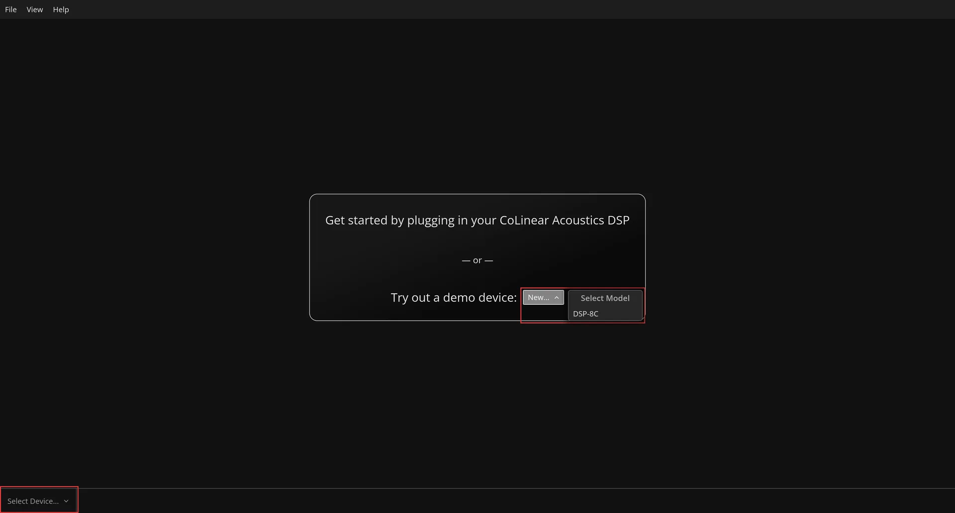
With no DSP connected, DSPconfig opens on a screen offering the two ways to get started: plug a unit in, or open a demo device.
Main Window
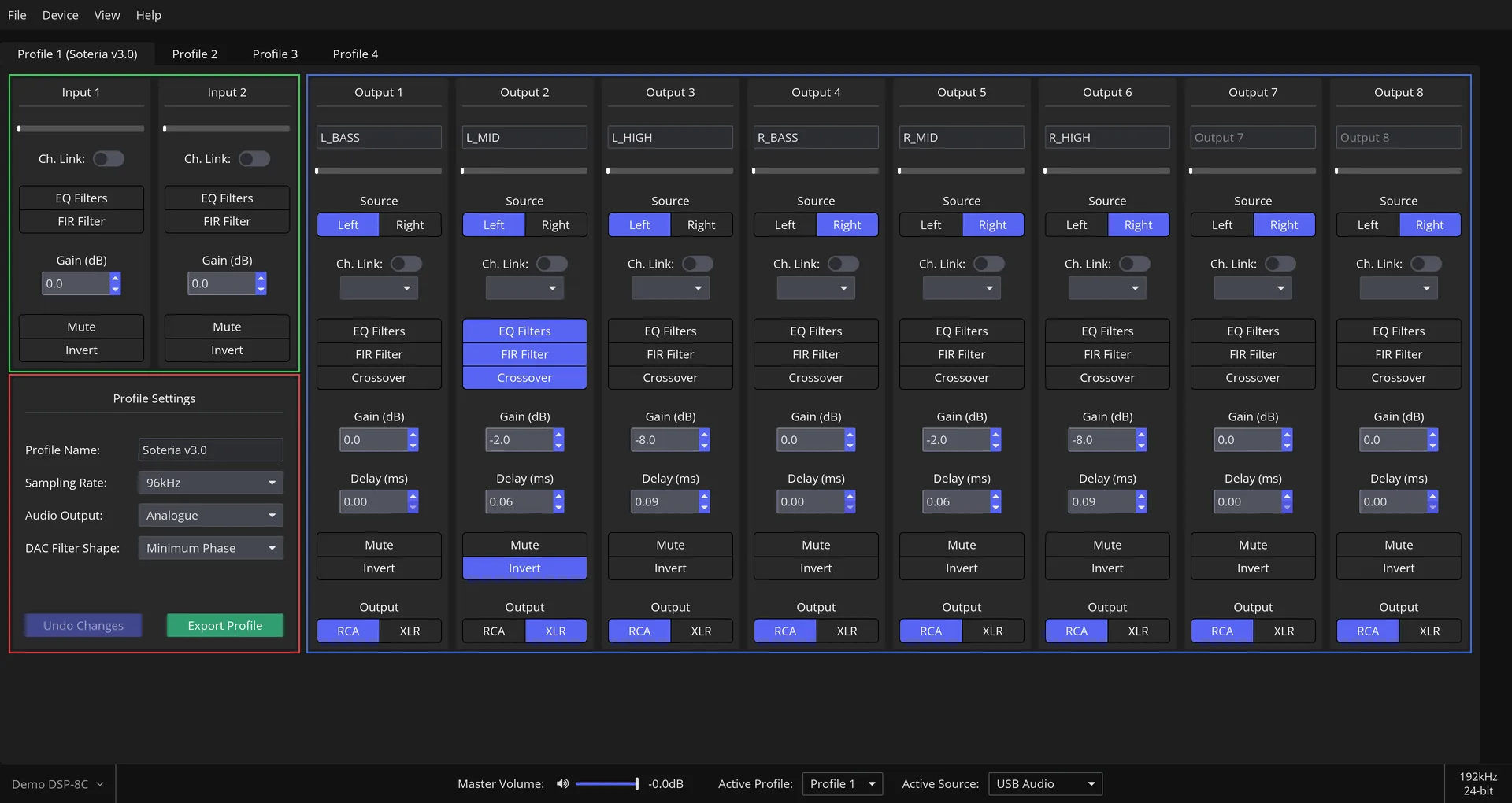
With your DSP device connected via USB and powered on, you will reach the main window for configuring your DSP. Several of the key areas are outlined.
Menu Bar
File
Actions apply to the profile in the currently selected tab.
| Item | Description |
|---|---|
Import Profile... | Reads a profile from a file into the selected slot, replacing what is there. |
Export Profile... | Writes the selected profile out to a file. |
Copy Profile... | Copies the selected profile into another slot on the same device. |
Save Changes | Uploads the selected profile to the device (not present for a demo device.) |
Undo Changes | Reverts the profile to the last state saved to the device. |
Reset Profile | Returns the profile to its factory defaults. |
Preferences | Opens Application Preferences. |
Exit | Closes DSPconfig. |
Device
Settings and configuration of the device itself, rather than of a profile.
| Item | Description |
|---|---|
Settings | Opens Device Settings: display brightness, display timeout, full-scale output voltage and volume mode. |
Firmware... | Reports the firmware the unit is running, and offers an upgrade when a newer version is available. Physical devices only. |
View
| Item | Description |
|---|---|
Zoom In (Ctrl + =) | Scales the whole interface up. |
Zoom Out (Ctrl + -) | Scales the whole interface down. |
Reset Zoom | Returns the interface to its default scale. |
Help
| Item | Description |
|---|---|
Visit Homepage... | Opens the CoLinear Acoustics website in your browser. |
Show Safety Message | Shows the safety notice presented on first run. |
Check for Updates | Checks whether a newer DSPconfig is available. |
About | Reports the DSPconfig version you are running. |
Profile Management
The DSP holds up to 4 profiles at once. Each one can be modified independently and can be switched between whilst audio is playing, allowing you to compare different set ups for the same system, or store set ups for different systems.
Input Channels
The two input channels, left and right, can be configured here.
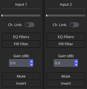
The available configuration options, in the order they appear on the card:
| Control | Description |
|---|---|
| Channel link | Mirrors changes made to this channel onto the other input channel. Only changes made after it is switched on are mirrored. |
EQ Filters | Opens the EQ Filter Editor for this channel. |
FIR Filter | Opens the FIR Filter Editor for this channel. |
Gain (dB) | This channel's overall gain, from -120.0 dB to +30.0 dB. Master volume is a separate parameter, applied after all other processing. |
Mute | Mutes this channel. |
Invert | Inverts the phase of this channel, equivalent to rotating the phase by 180 degrees. |
Live level/hold meters are also displayed at the top of the input channel cards, allowing you to visualise the level of the audio passing through each channel. There is no clip indicator on the input channels because processing takes place using floating point arithmetic capable of representing intermediate values that exceed full scale output. audio signals are only clipped to the minimum/maximum values when they get converted back to standard PCM values immediately before being sent onwards to the DAC.
Output Channels
These cards are where each output channel is configured independently; 8 channels for the DSP-8C and 4 for the DSP-4C.
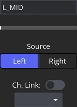
The available configuration options, in the order they appear on the card:
| Control | Description |
|---|---|
| Channel name | A personalised alias, to identify which driver this channel feeds. Up to 12 characters, basic alphanumerics and punctuation. |
Source | None, Left, Right, or both together, where Left is input channel 1 and Right is input channel 2. Selecting both is the simple sum of the two. |
| Channel link | Mirrors changes made to this channel onto the output channel you select. Only changes made after it is switched on are mirrored. |
EQ Filters | Opens the EQ Filter Editor for this channel. |
FIR Filter | Opens the FIR Filter Editor for this channel. |
Crossover | Opens the Crossover Editor for this channel. |
Gain (dB) | This channel's overall gain, from -120.0 dB to +30.0 dB. Master volume is a separate parameter, applied after all other processing. |
Delay (ms) | Delay on this channel, typically to time-align drivers, or channels carrying FIR filters of different lengths. Hovering the field shows the approximate distance that delay corresponds to. |
Mute | Mutes this channel. |
Invert | Inverts the phase of this channel, equivalent to rotating the phase by 180 degrees. |
XLR / RCA | Whether this channel's analogue audio leaves over the balanced XLR or the single-ended RCA connector. Useful when, for example, the drivers connect over XLR and the subwoofer over RCA. |
As with the input channel cards, a level/hold meter is displayed. Additionally, the meter will indicate whether the audio signal had to be clipped, by turning and staying red for several seconds.
Profile Settings
Each profile has a range of settings that apply to the profile as a whole, rather than the per-channel settings that have been discussed up to this point.
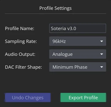
The available settings:
| Setting | Description |
|---|---|
Profile Name | Optionally, a descriptive alias for the profile. Up to 14 characters, basic alphanumerics and punctuation. |
Sampling Rate | The rate the input audio is resampled to, either 96kHz or 192kHz. |
Audio Output | Analogue or digital. Digital output currently carries only the two input channels, after processing has been applied to them. |
DAC Filter Shape | Which of the DAC's built-in oversampling filters is applied during conversion. |
Biquad and FIR coefficients are sample-rate sensitive, so when entering raw EQ filter or FIR coefficients, make sure they were produced for the rate the profile runs at. Operating at 192kHz also roughly halves the number of FIR taps the device can process; both figures are in Capacities.
Our hardware uses an extremely high quality asynchronous sample rate converter integrated within the core signal processing chip, so we recommend disabling any sample rate conversion performed by your operating system or media player and letting the DSP handle it itself.
The DAC filter shape defaults to Minimum Phase, which suits most users. The top of the range ESS DACs in our devices use an oversampling filter to achieve their class-leading specification, and we expose the choice of which one for those who want it; you are free to try any of the options and pick whichever you feel results in the best audio signature to your ears. Differences between the settings are likely to be small.
From here, you can also click Undo Changes to revert the settings to the previously saved state, or Save Changes to upload them to the DSP. The capture above is of a Demo Device, which has no DSP to save to: there Undo Changes is greyed out and the second button reads Export Profile instead, which writes the profile to a file.
The Status Bar
The bar along the bottom of the main window carries three things: which device you are editing, direct control of playback, and what the incoming audio actually is.
Device Selector
When one or more DSPs are connected to DSPconfig, you can select between them using device selector located at the bottom left of the window. The currently active device is the one named when the selector is closed and, when the selector is open, the active device is indicated by a green circle.
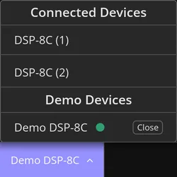 Two units of the same model are numbered in the order they were found,
 DSP-8C (1) and DSP-8C (2), so a bench with several attached stays unambiguous.
Demo devices always appear as an entry in the selector. If one hasn't been created yet, a New button is shown, and if one has been created, a Close button is shown.
Audio Controls
DSPconfig exposes direct control of several audio playback parameters. The Master Volume: slider adjusts overall level, and the speaker icon beside it toggles mute. Active Profile: and Active Source: are drop down boxes that switch the running profile and the audio input without going through a menu.
Current Sampling Rate and Bit Depth
In the far bottom right, the sampling rate and bit depth of the incoming audio stream are displayed. When the input source is USB Audio, these figures are what the connected computer negotiated over USB Audio Class 2.0. For a digital source, they are what the S/PDIF receiver reports. Either reading shows --kHz and --bit when no format can be determined, which is what you see when a digital input is selected but nothing is connected to it.
Settings
Application Preferences
Reached from File > Preferences. These belong to DSPconfig itself rather than to any device or profile, and apply whichever device is selected.
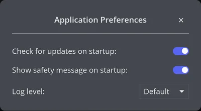
| Setting | Description |
|---|---|
Check for updates on startup: | Whether DSPconfig looks for a newer version each time it opens. |
Show safety message on startup: | Whether the safety notice is presented on each run. |
Log level: | How much detail DSPconfig records in its log. |
Device Settings
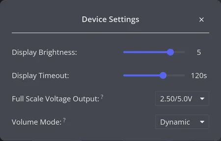
Reached from Device > Settings. These belong to the device rather than to a profile, so they are the same whichever profile is active.
| Setting | Description |
|---|---|
Display Brightness: | Six levels. |
Display Timeout: | How long the display stays lit: never, 30, 60 or 120 seconds. |
Full Scale Voltage Output: | The output level 0 dBFS corresponds to, chosen as a single-ended and balanced pair: 2.00 to 2.50 V single-ended in 0.05 V steps, with the matching 4.00 to 5.00 V balanced figure. |
Volume Mode: | Dynamic operates the unit as a preamplifier with volume control. Fixed bypasses the internal volume control and outputs at full scale. |
Before selecting Fixed, make sure downstream amplification is reduced. In that mode the unit outputs at 0.0 dB whatever the volume control says, which can damage your speakers if the amplifiers after it are set for a lower level.
A demo device has these settings too. Nothing behind them changes, since there is no hardware, but they behave as they do on a real unit. Device > Firmware... is the one item a demo does not get.
Filter Editor Window
A secondary window is used to give precise control over the configuration of EQ filters, FIR filters and crossovers. Within the filter editor window, you can quickly jump from one filter type or channel to another using the drop down boxes at the top left, or save and export your changes using the button at the top right.
EQ Filter Editor
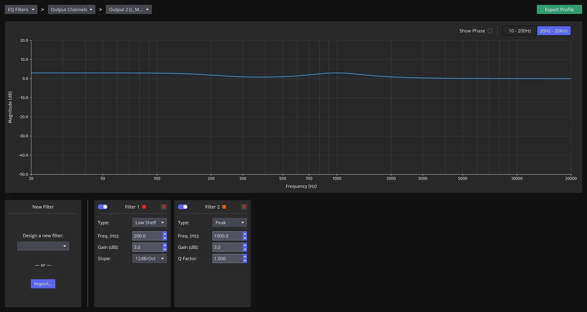
In the Main Window, click on the EQ Filters button to open the EQ Filter Editor for that channel. From here, you can either manually design your EQ filters by selecting the filter type from the drop down box and amending the parameters, or you can import a filter file from another program.
When designing filters manually, select your filter from the drop down list, amend the parameters and press the green + button to add it to the active filter list. Press the red x button to delete it. You can click the blue toggle button to enable/disable individual filters.
As you add filters, they will be displayed on the graph. You can toggle the phase to view the impact the filters have on phase. You can toggle the range of the frequency depending on which area you are applying filters to.
Each filter is one biquad. How many biquads a single channel may hold, and how many the input and output channels hold between them, are in Capacities.
The Filter Type list offers twelve shapes, in this order:
| Filter | Description |
|---|---|
Peak | The default: a peaking or parametric band, set by frequency, gain and Q. |
Notch | A deep, narrow cut at one frequency. |
High Shelf, Low Shelf | Shelving filters set by frequency, gain and slope. |
High Shelf RBJ, Low Shelf RBJ | The Robert Bristow-Johnson formulation of the same two, which places the gain reference differently. |
High Shelf Q, Low Shelf Q | Shelving filters specified by Q rather than by slope. |
All Pass, All Pass Q | Phase-only filters, first or second order, which leave magnitude untouched. |
Linkwitz Transform | Re-shapes a sealed driver's low-frequency roll-off from one Q and corner frequency to another. |
Custom | Raw biquad coefficients, typed or pasted in. |
Exporting EQ filters from REW. In the EQ Filters window in REW, set the EQ to Generic → Extended. Click Export filter settings as text, or Export filter settings as formatted text - DSPconfig natively parses either, and neither one asks you to specify a sample rate first.
Save filter coefficients to file, exported as miniDSP or SigmaStudio, also works and DSPconfig will parse it too, but it is an extra step - choosing the sample rate your DSP is running at - for no benefit over the plain text export above.
FIR Filter Editor
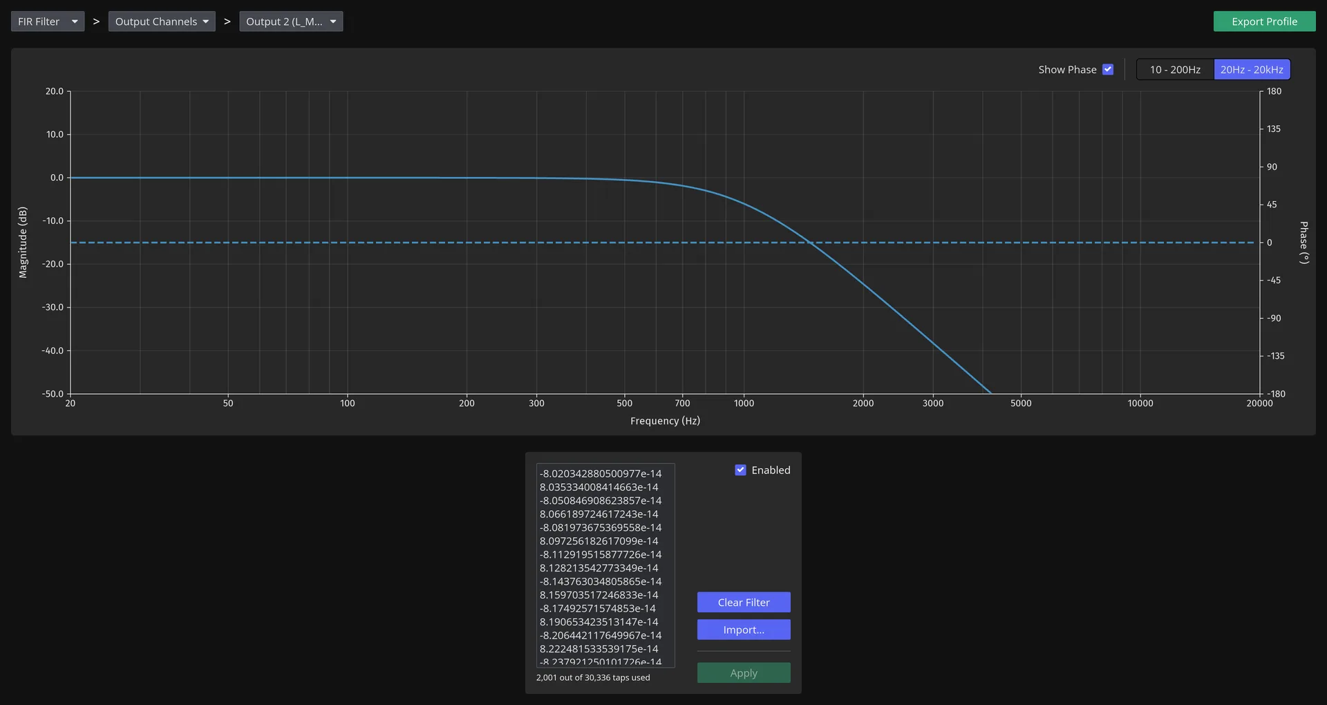
Click on a channel's FIR Filter button to open the FIR Filter Editor for the corresponding channel. Import... accepts four coefficient formats and chooses between them by the file's extension: .txt for one number per line, .csv for numbers separated by commas, .bin for raw 32-bit floats and .dbl for raw 64-bit floats. These formats align with the equivalent export format in rePhase. Always make sure that your coefficients are generated against the correct sampling rate (configured in the Profile Settings), otherwise the filter shape may look correct, but the cut off frequency will not be. Coefficients can also be typed or pasted into the editor by hand; whichever way they arrive, Apply is what commits them to the channel. The graph will display the filter, and you can toggle the frequency range and phase response.
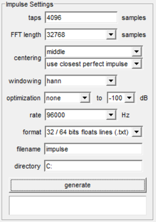
Exporting FIR filters from rePhase. Once you have created your FIR filter in rePhase you will need to specify the settings before exporting it for DSPconfig. The rate should be set to the processing rate used on your profile, and the format should be 32 / 64 bits floats lines (.txt). An example of the settings for an output channel using 4096 taps at 96kHz:
Crossover Editor
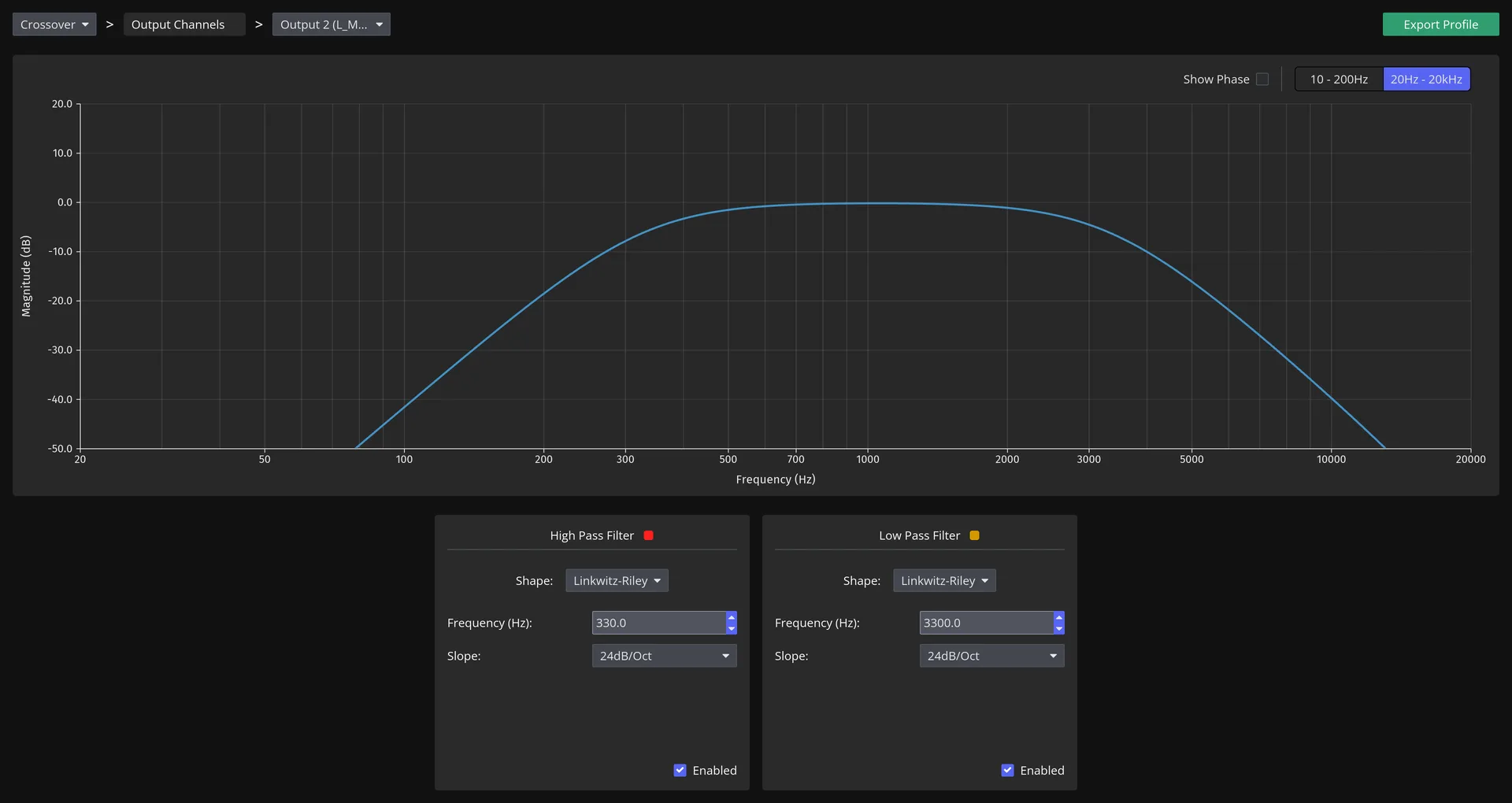
Each output channel can support a low pass and/or a high pass crossover filter. Select your desired shape from the drop down box and amend the parameters as required.
The Shape list offers None, Bessel, Butterworth, Chebyshev1, Chebyshev2 and Linkwitz-Riley. Each takes a corner frequency and a slope, and three of them take one parameter of their own: Bessel a normalisation, Chebyshev1 a passband ripple and Chebyshev2 a stopband attenuation.
Slopes run from 6 dB/octave to 48 dB/octave in 6 dB steps, except for Linkwitz-Riley, which is defined only at 12, 24, 36 and 48 dB/octave.
The graph will display the filter, and you can toggle the frequency range and phase response.
Capacities
Processing capacity depends upon device model and output sampling rate, detailed in the table below.
| Resource | DSP-8C | DSP-4C |
|---|---|---|
| Profiles | 4 | 4 |
| Output channels | 8 | 4 |
| EQ biquads, both input channels combined | 60 | 60 |
| EQ biquads, max per output channel | 64 | 64 |
| EQ biquads, all output channels combined | 288 | 256 |
| FIR taps, both input channels combined @ 96kHz | 16,384 | 16,384 |
| FIR taps, both input channels combined @ 192kHz | 9,216 | 9,728 |
| FIR taps, all output channels combined @ 96kHz | 36,864 | 36,864 |
| FIR taps, all output channels combined @ 192kHz | 18,432 | 18,432 |
| Delay, all output channels combined @ 96kHz | 1,600 ms | 1,600 ms |
| Delay, all output channels combined @ 192kHz | 800 ms | 800 ms |
| Delay, max per output channel | 655.35 ms | 655.35 ms |
Demo Mode
DSPconfig allows you to create a so-called "Demo Device", which allows you to test the application without having a physical device on hand to connect. All of the main features can be used, giving you ability to plan a system, learn how to use the software or to build a profile before your unit arrives.
Demo devices can be created either from the opening screen when no other device is connected, using the New... button under Try out a demo device, or at any time from the device selector at the bottom left of the main window.
Use the Export Profile button or menu item to save a profile that you've built in demo mode, which you can then import to a physical device at a later date.