
FIR vs IIR Crossovers in Active Loudspeaker Design
This note explains the practical differences between Infinite Impulse Response (IIR) and Finite Impulse Response (FIR) filters when used for crossovers and correction in active loudspeaker systems, and when each approach is appropriate. Both are widely used and well understood; the right choice depends on the requirements of the system rather than any single “best” method.
Introduction
Digital signal processing plays a central role in modern active loudspeaker systems. At its simplest, DSP enables crossover implementation and frequency response shaping. As system requirements increase, attention extends beyond magnitude response to phase behaviour, time alignment, and room correction.
IIR and FIR filters are the two primary filter types used in this context. They offer different capabilities and trade-offs when applied to crossover design and system correction, which we will set out in the following sections.
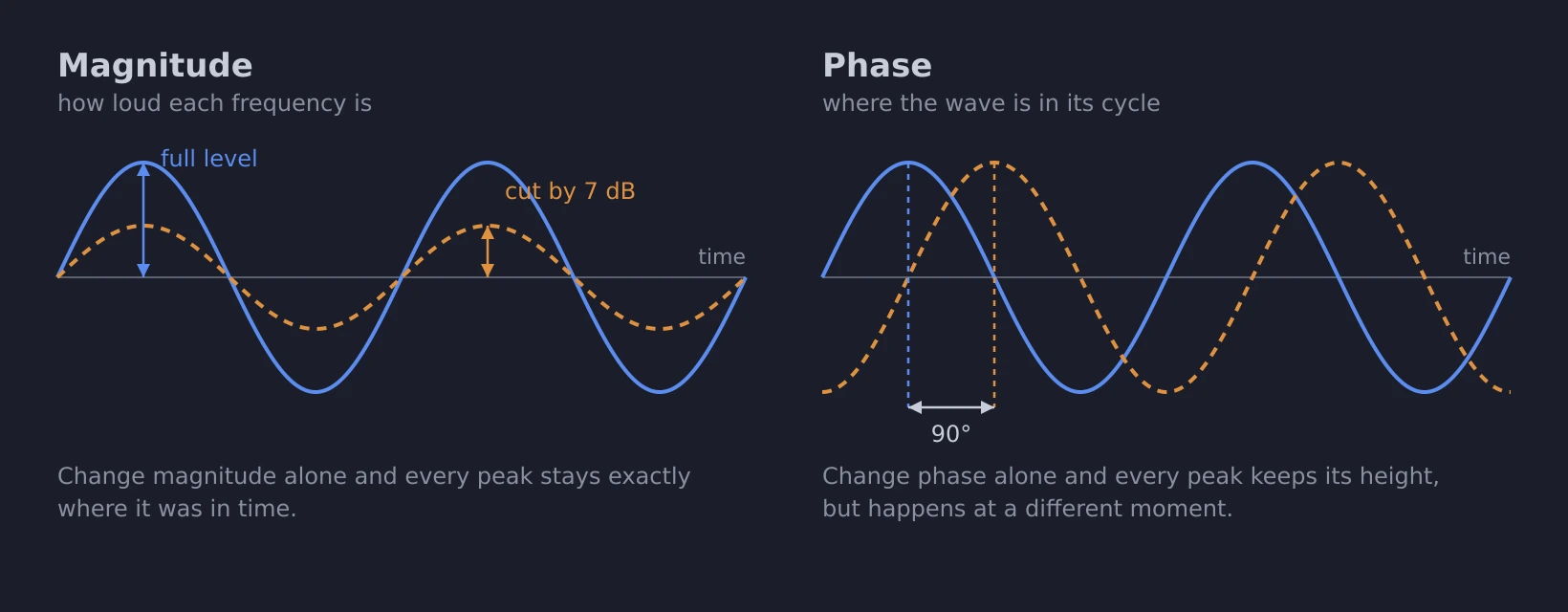
Both filter types work on two separate aspects of the resulting sound wave: its magnitude and its phase. Magnitude is the simpler one to reason about and visualise - it is how loud each frequency is. Phase describes where the sound wave is in its cycle, and it is what decides how the output of one driver adds to the output of the next through the region where both are playing.
IIR filtering with biquads
IIR filters are the most commonly used approach for crossover implementation in both analogue and digital systems. Their typical characteristics are that they are computationally efficient, introduce very little latency, use well-established filter topologies such as Butterworth and Linkwitz-Riley, and are straightforward to implement.
The filter types used for crossovers and equalisation - Butterworth, Linkwitz-Riley, the shelves and bells of a parametric EQ - begin life as an analogue prototype: a mathematical description of how the filter would behave as an analogue circuit of resistors, capacitors and inductors. Such a prototype is a continuous-time object, defined at every instant and at every frequency. However, digital signal processing works in discrete steps, so the prototype has to be converted. That conversion is where the sampling rate of the DSP has to be declared - 96kHz or 192kHz on our products - and what comes out of it is a set of coefficients.
Those coefficients are applied by the IIR difference equation, which computes each output sample from the recent input samples and from the filter's own recent output samples:
It is that second half, the filter reading back its own output, that makes the impulse response "infinite": feed in a single sample and something of it is still circulating long afterwards.
An IIR filter can be of any order , and the order is what determines how steep a slope it can realise: dB/octave, for one coefficient of memory per 6 dB.
| Order | Difference equation | Slope | Coefficients |
|---|---|---|---|
| 1 | 6 dB/octave | 3 | |
| 2 | 12 dB/octave | 5 | |
| 3 | 18 dB/octave | 7 | |
| as above, to and | dB/octave |
However, the higher the order, the more sensitive the coefficients are to rounding precision, and the less accurate the filter becomes. Instead, longer filters are split up into individual 2nd-order filters and processed one after the other. The end result is the accuracy of lower order filters combined with the steepness of higher order filters. These 2nd-order filters are our biquads.
Everything required by a conventional crossover or room correction is composed of one or more of these biquads: a 12 dB/octave slope is one biquad, the 24 dB/octave Linkwitz-Riley of Fig. 3 is two, and a parametric EQ band is one apiece. This also explains why a DSP's IIR capacity is quoted as a number of biquads rather than a number of filters - 348 on the DSP-8C, 316 on the DSP-4C.
Note that IIR filters give you free control over only one of those two components at a time. We manipulate the magnitude response freely with our biquads - the slopes of the crossovers, the boosts and cuts of a peaking filter - and we are left with whatever phase response comes with them, which is not ours to choose. The mirror image of that is the all-pass filter, which does the reverse: it leaves the magnitude response flat and shifts the phase.
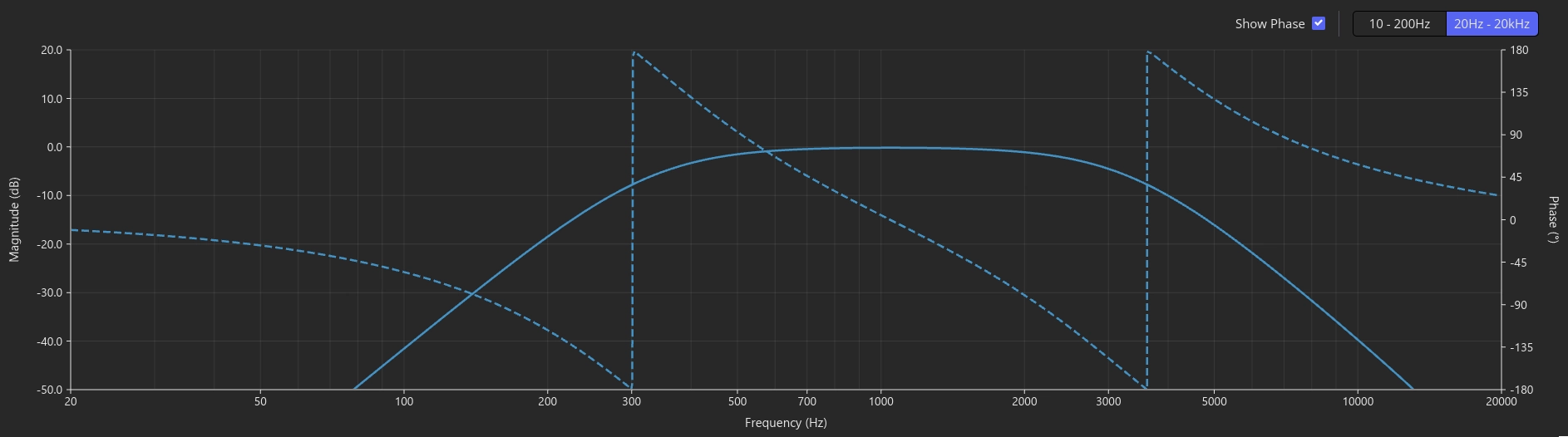
Fig. 3 shows a typical Linkwitz-Riley bandpass, here the passband for a midrange driver in a three-way system, formed by a high-pass at 330Hz and a low-pass at 3300Hz, both 24 dB/octave. The solid trace is magnitude; the dashed trace is phase. The characteristic phase rotation through each crossover region is clearly visible.
FIR filtering
FIR filters differ fundamentally in that they allow independent control over both magnitude and phase response, meaning that we can design linear or arbitrary-phase filters. With this increased flexibility come some important trade-offs: computational requirements are much higher, and latency is proportional to filter length.
Whilst a single biquad is only comprised of 5 coefficients, a single FIR filter can easily require hundreds to thousands of taps (coefficients). As a rule of thumb, shaping lower frequencies and running at a higher sampling rate both increase the number of taps a given filter response needs.
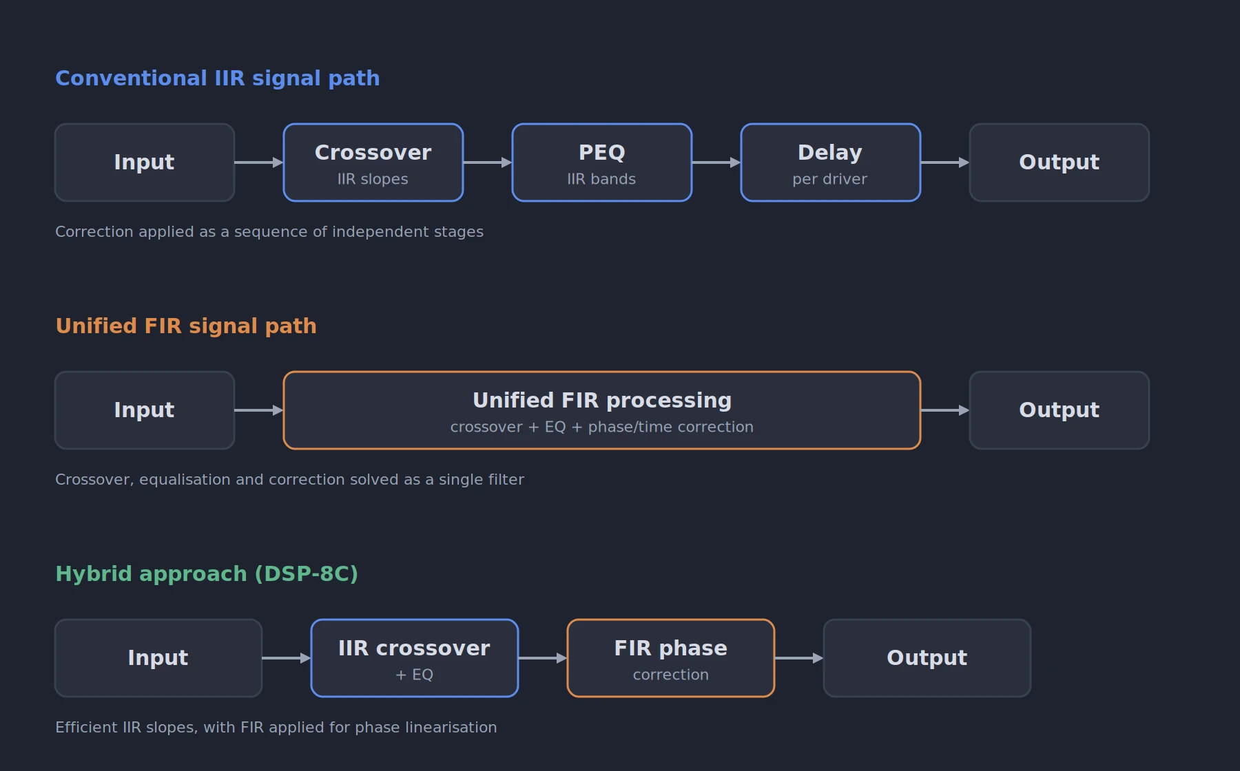
In a loudspeaker system, FIR filters can be used to implement crossover functions, correct driver magnitude and phase response, and align acoustic output without relying solely on delay. Because an FIR filter can incorporate multiple functions within a single structure, crossover behaviour and correction can be treated as a unified problem rather than a sequence of independent steps.
Combining IIR and FIR
The two approaches are not mutually exclusive. A practical and increasingly common method is to use IIR filters for the crossover slopes and equalisation, where they are efficient across the full frequency range and at any sampling rate, and then apply an FIR filter purely to linearise the resulting phase. This is exactly the pairing in Figs. 3 and 4: the IIR bandpass defines the magnitude response, and the FIR filter corrects the phase without altering that magnitude.
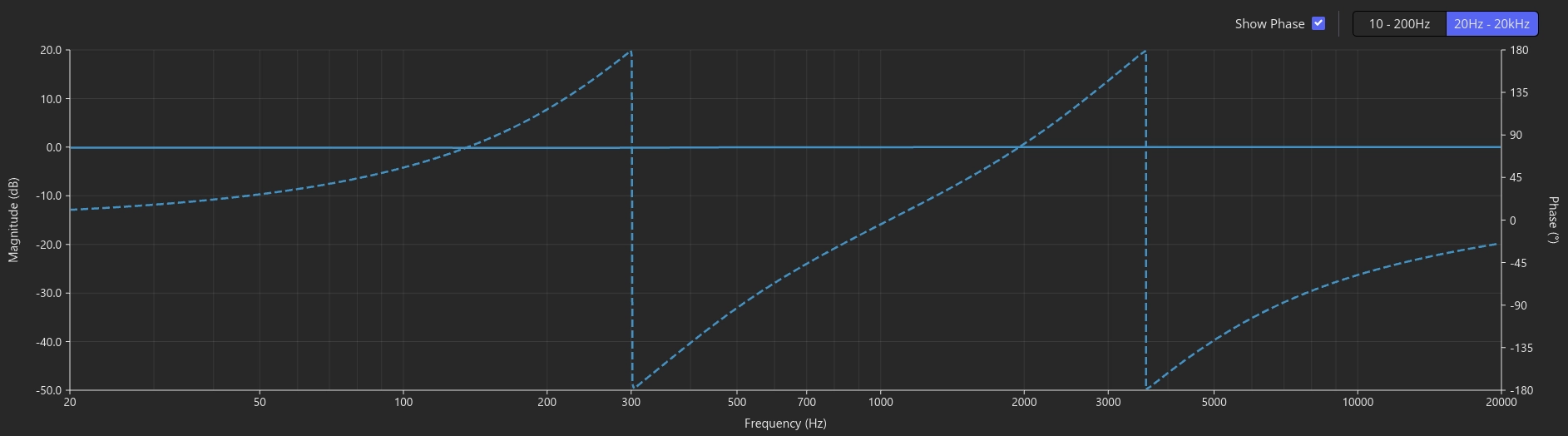
Fig. 4 shows an FIR filter generated to linearise the phase of the bandpass in Fig. 3. The magnitude response is left unchanged (it is a phase-only correction) while the phase is adjusted by an equal and opposite amount to the IIR crossover. Applied together, the two produce the same bandpass magnitude response but with a flat phase response.
This hybrid approach keeps the computational cost of the magnitude shaping low, while reserving FIR resources for the task where they add the most value. It also sidesteps a fundamental limitation of FIR filters: frequency resolution is tied to filter length, so controlling low frequencies with FIR alone requires very long filters, and correspondingly high latency. Using IIR for the low-frequency crossover slopes and FIR for phase correction avoids spending a large tap budget simply to reach down in frequency. The DSP-8C supports both filter types on every channel, so this combination can be implemented directly: IIR crossovers and EQ designed in DSPconfig, with a phase-correcting FIR filter (for example generated in rePhase) loaded alongside them.
Phase behaviour and time-domain response
An IIR crossover shifts some frequencies more than others, so a signal that passes through it comes out with its components in a slightly different time relationship than they went in. An FIR filter can be built to shift every frequency by the same amount instead, which is what linear phase means. In other words, the sound is delayed, but it arrives with its shape intact.
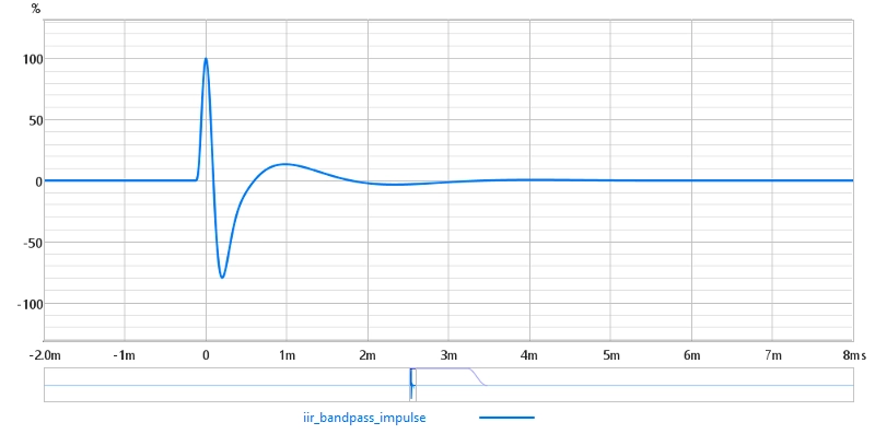
That linearity comes at a cost, which is that a linear-phase filter is symmetrical - a concept that is best explained visually. Fig. 5 is the impulse response of the IIR bandpass on its own, which starts sharply at and decays smoothly. Fig. 6 is the same bandpass with the FIR correction, and quite a different shape is seen. Instead of the impulse response starting with the sharp peak, there is some low-level ripple that precedes the peak. Indeed, it is a mirror image of the impulse response's post-peak decay. This low-level ripple before the peak is known as pre-ringing, and represents sound that reaches the listener before the sound that actually caused it.
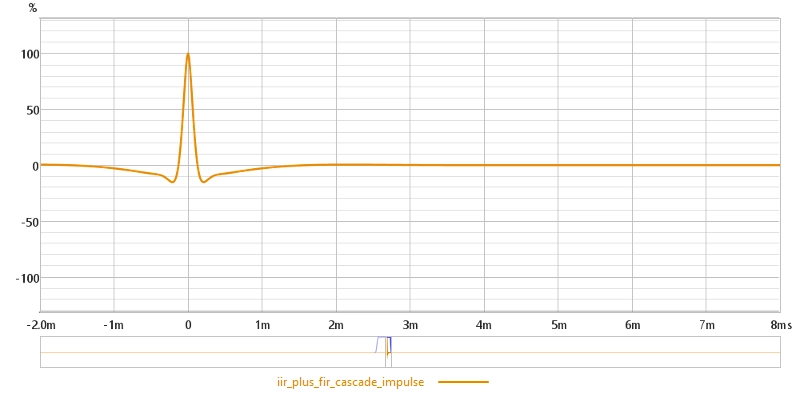
Whilst this may seem like a significant disadvantage, it's worth doing a back-to-back listening test with material that you are familiar with (our DSPs support multiple profiles, so you can have one pure IIR profile, and one that has phase linearisation on top). Many listeners actually find the phase-corrected version to be an audible improvement, with it being more coherent through the crossover.
Latency considerations
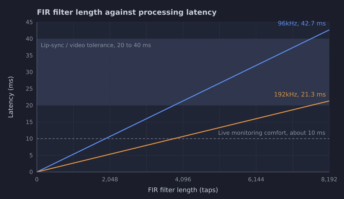
Latency is an inherent consideration in FIR-based processing. IIR filters introduce negligible latency, only the small group delay of the filter itself. Linear-phase FIR filters introduce a fixed latency proportional to the number of taps: short filters introduce modest latency, while longer filters used for higher resolution or lower-frequency control increase it. (Minimum-phase FIR designs avoid this fixed delay, but give up the linear-phase property that is usually the reason for using FIR in the first place.)
For most playback applications this latency is not perceptually significant, but it is very relevant in contexts requiring synchronisation with video, or real-time monitoring. Fig. 7 shows the relationship between filter length and latency at 96kHz and 192kHz. Note that operating at the higher sample rate halves the latency for a given tap count, though it also roughly halves the number of taps available. The eight output channels draw on a shared pool of 36,864 taps at 96kHz, or 18,432 at 192kHz, so on any one channel it is the latency rather than the pool that runs out first.
Practical workflow differences
An IIR-based workflow generally involves selecting a crossover topology, applying parametric equalisation, adjusting delay for alignment, and iterating based on measurements. It is typically fast to implement and well supported by integrated DSP platforms.
A FIR-based workflow generally involves measuring the driver and system response, defining the target magnitude and phase behaviour, designing filters (often in a dedicated tool), and implementing them within the DSP system. It provides greater flexibility but requires more detailed measurement and design work.
Application considerations
In practice, both approaches are valid and widely used. IIR-based systems are well suited to applications requiring low latency, rapid deployment and iteration, and systems where conventional crossover behaviour is sufficient. FIR-based systems are often used where control over phase response is a priority, where crossover and correction are treated as a unified problem, and where sufficient processing resources are available. The appropriate choice depends on system requirements rather than a single “best” method.
Summary
IIR and FIR filters represent two complementary approaches to active crossover design. IIR filters provide efficient, low-latency solutions that are widely used and well understood. FIR filters offer additional flexibility, particularly in controlling phase and time-domain behaviour, at the cost of increased computational demand and design complexity, along with the inherent pre-ringing of linear-phase processing.
Modern DSP platforms increasingly support both approaches, and the two can be combined to good effect: using IIR for efficient magnitude shaping and FIR for phase linearisation. This allows system designers to select, or blend, the most appropriate method for a given application.
Further reading
Getting Started with DSPconfig - configuring crossovers, EQ and FIR filters on the DSP-8C.