
Getting Started with DSPconfig
Applies to the DSP-8C and the DSP-4C.
DSPconfig is the control software for setting up your DSP device with your crossovers, filters and other DSP parameters. This guide is the path through it: install the software, look around without any hardware attached, connect your DSP, and build a working profile from an empty one. It is meant to be read in order the first time.
It is deliberately not a list of every control. If you already know what you are looking for, the DSPconfig Reference describes each window and each control in turn, and gathers every capacity figure into one table at the end.
Installing DSPconfig
DSPconfig runs natively on Windows, macOS and Linux. The Downloads page carries the current build for each, with the install steps for that platform underneath it: a portable executable on Windows, a disk image on macOS with separate Apple silicon and Intel builds, and a Debian package on Linux, which also installs the USB rules DSPconfig needs in order to see your DSP at all. If you have any issues with downloading or installing the software, please contact us at [email protected].
The first time you launch it, DSPconfig opens on a Caution notice before anything else. It covers two things worth reading once: use an in-line capacitor to protect your tweeters, and power your system up and down in the right order, which is sources and DSP on first and amplifiers on last, then amplifiers off first on the way back down. Press I Understand to continue. Clearing "Always show on startup" stops it appearing again; Help, then Show Safety Message, brings it back whenever you want it.
Demo Mode
With no DSP attached, DSPconfig opens on a screen offering two ways forward: plug in your CoLinear Acoustics DSP, or try out a demo device.
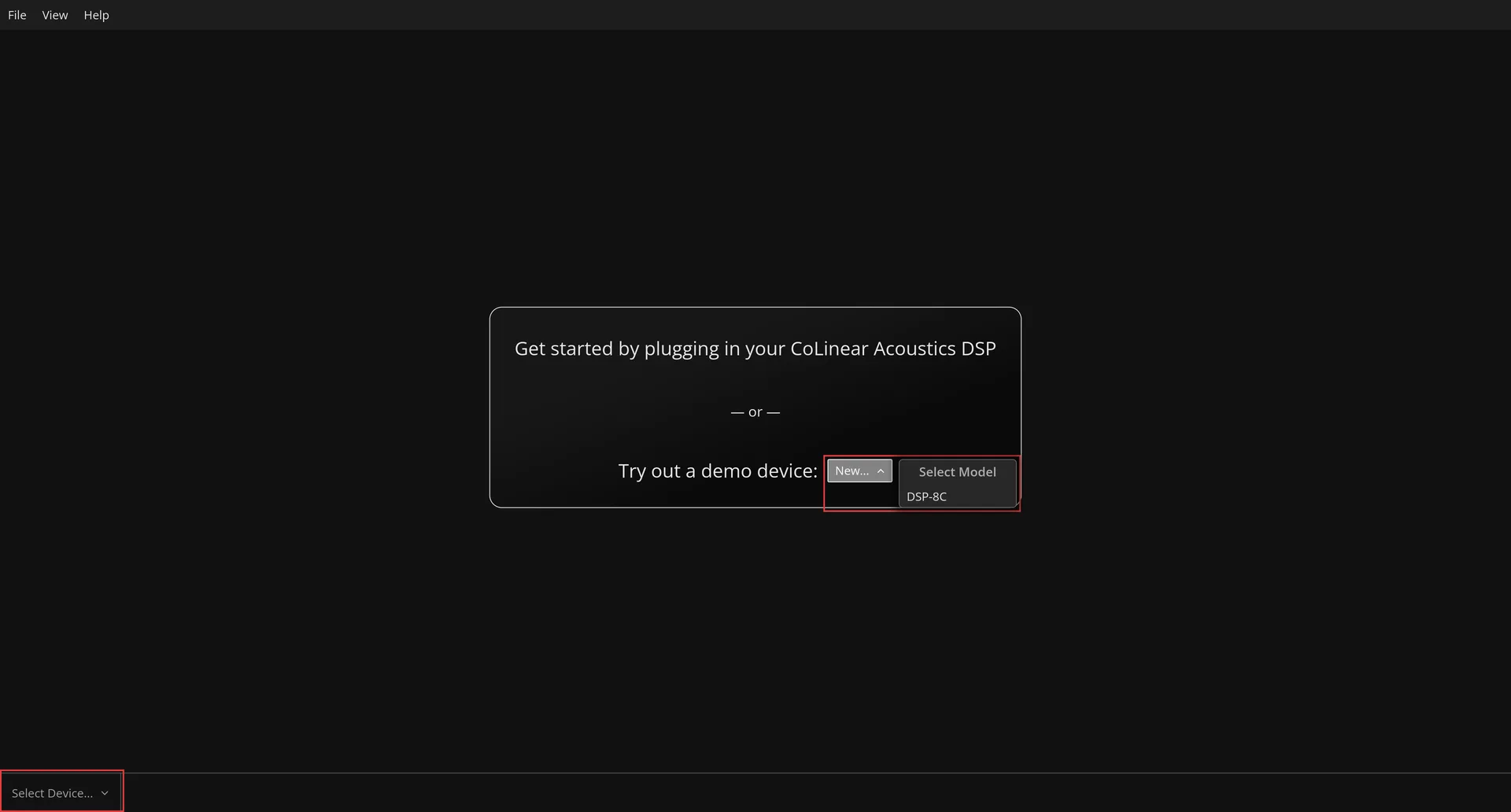
You can use the Demo Mode to enter DSPconfig without having a DSP device connected. In this mode, you can fully evaluate the capabilities of DSPconfig and export profiles that you create. Press New beside "Try out a demo device" and choose from the models it offers, and DSPconfig opens the full editor against a device that exists only in the application. Every window, every control and every filter editor behaves as it does on real hardware.
The one thing a demo device cannot do is save to a DSP, because there is not one behind it. Where a connected device offers Save Changes, a demo offers Export Profile, which writes the profile out to a file instead. A profile built in Demo Mode is therefore not wasted work: export it, and import it onto a real device later.
The drop down box in the bottom left hand corner of the window switches between everything DSPconfig currently has open, so you can move between a Demo Device and a connected one at any time - and, from DSPconfig 1.5.0, between several connected devices. It lists connected devices first and demo devices below them, and each demo carries its own Close button for when you are finished with it.
Connecting Your DSP
Connect the DSP to your computer with a USB cable and switch it on. Nothing else is needed: DSPconfig watches for the device itself, reports "DSP-8C connected" as it appears, and adds it to the selector in the bottom left corner, where a physical unit is labelled with its model and the word Connected. It then reads the profiles off the device, and each profile tab fills in as its own read lands, so a tab may briefly say it is still reading.
If a device is detected but cannot be opened, DSPconfig says so rather than failing quietly, and the message names the reason. The two common ones are another instance of DSPconfig already holding the device, and a unit whose firmware is newer than this build of DSPconfig understands, which is fixed by updating DSPconfig rather than the device.
A device also brings a Device menu to the menu bar, holding up to two items. 'Device → Firmware…' appears for a physical unit and reports the firmware your DSP is running, offering an upgrade when DSPconfig carries a newer one. 'Device → Settings' controls the display brightness, display timeout, full-scale output voltage and volume mode; it appears only once your DSP is running firmware 1.6, which is the version those settings were introduced in. A unit on earlier firmware still gets the Firmware item, which is how you reach the upgrade that adds them. Both are described in Keeping DSPconfig and Your Firmware Current, below.
Main Window
With your DSP device connected via USB and powered on, you will reach the main window for configuring your DSP.
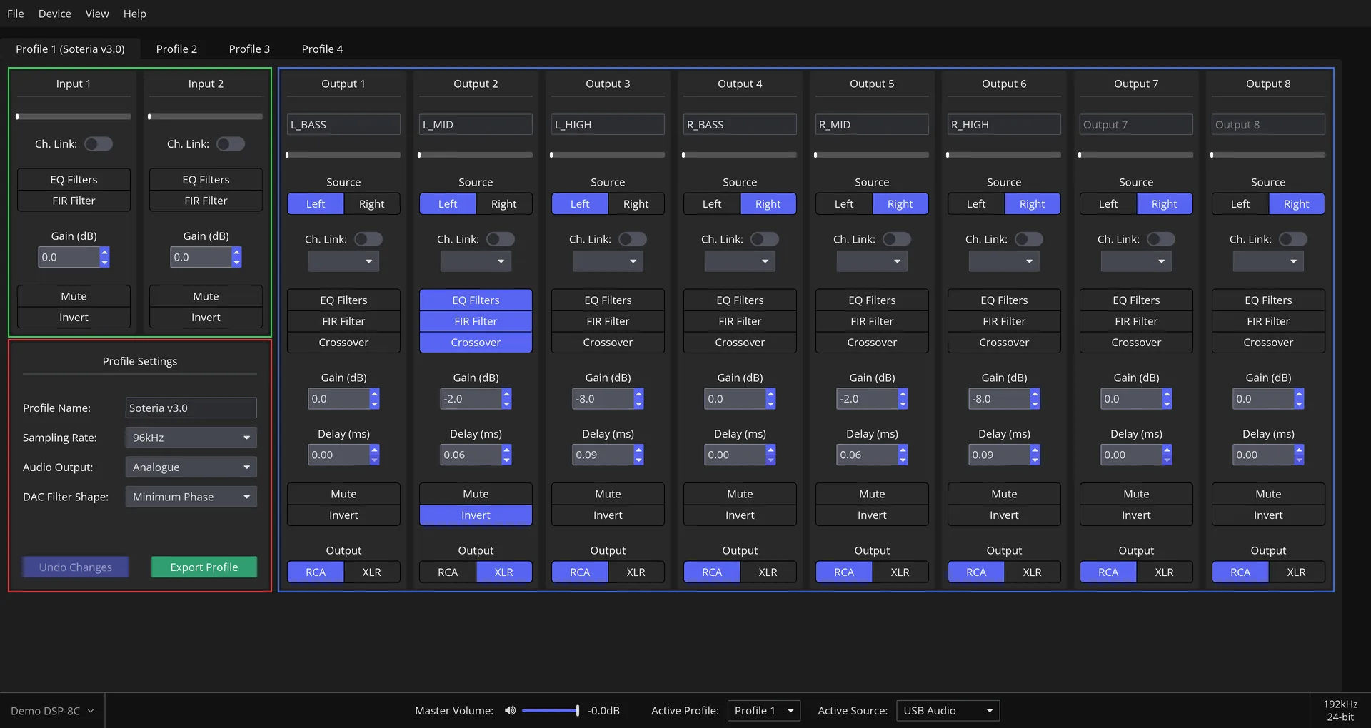
Four things share this window:
- The profile tabs across the top. The DSP holds several profiles at any one time, each of them a complete and independent set up, and the tabs are how you move between them. A tab is labelled with its number and, once you give the profile a name, that name as well. It grows an asterisk while the profile has changes you have not saved yet, which makes the tab bar the quickest way to see what is still outstanding.
- The two input channels, top left. Each one carries EQ and FIR filters, a gain, a mute and a phase invert, and the Ch. Link toggle mirrors one channel's settings onto the other.
- Profile Settings, below the input channels. The settings that belong to the whole profile rather than to any one channel, and the two buttons that commit it.
- The output channels, filling the rest of the window. One column per channel, each independent of the others.
Along the foot of the window sit the device selector, the master volume, the profile the device is currently playing and the source it is playing from. Those report and control the device itself rather than the profile you are editing.
The capture above is a Demo DSP-8C carrying a finished three-way stereo profile: a bass, mid and high output for each of the left and right channels, with the last two output channels unused. That is the profile the next section builds from nothing.
Building Your First Profile
A profile you have never touched does nothing at all. Every output channel starts sourced from neither input, which means silent, so the work below is what turns a connected DSP into a working loudspeaker.
The example is the three-way stereo system in the capture above, on a DSP-8C. A DSP-4C has fewer output channels, so the same steps build a two-way stereo system on one; nothing else about them changes. How many channels each model has is in the reference's Capacities table.
Pick the profile tab you want to build in first. Everything below applies to that profile alone, and the other profiles are untouched.
Choose the sampling rate
Start in Profile Settings, and start here rather than anywhere else, because this choice sets the ceiling on everything after it.
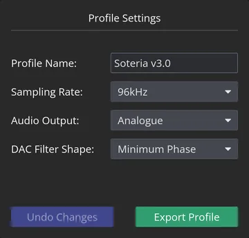
Give the profile a name in Profile Name, up to fourteen characters. The name appears on the tab, so it is worth the few seconds when you have four profiles and want to know which is which.
Sampling Rate is the choice between 96kHz and 192kHz. Running at 192kHz leaves the processor half as long to spend on each block of audio, so the FIR tap budget at that rate is roughly half of the one at 96kHz. Nothing stops you changing it later, but a profile designed at 96kHz may no longer fit at 192kHz, which is why it belongs at the start. The reference's Capacities table gives the figures for both rates on both models.
Audio Output selects between the analogue outputs and S/PDIF. When the digital output is in use, only the two input channels are processed. DAC Filter Shape selects the reconstruction filter the DAC uses, and which shapes are offered depends on the device.
Name and source each output
Now work across the output channels. The top of each column decides what that channel carries.
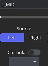
The text box at the top of the column takes a name of up to twelve characters. Until you type one, the channel's own number shows in grey. Naming the channel is not decoration: the name follows it into the filter editor's channel picker, so you choose "L_MID" from a list rather than counting columns to find Output 2.
Source is a pair of buttons, Left and Right, not a drop down. Light Left for a channel fed from Input 1, light Right for a channel fed from Input 2, or light both for a channel fed from both inputs. Pressing a lit button turns it off again, and a channel with neither lit takes no input at all and stays silent. That is the state every channel of an untouched profile is in, and it is the single most common reason a freshly set up DSP makes no sound.
For the example, that is Left on the three channels named L_BASS, L_MID and L_HIGH, and Right on R_BASS, R_MID and R_HIGH.
Ch. Link, below Source, ties this channel to another output channel: turn the toggle on and pick the partner from the list underneath. Linked channels move together from then on, so an edit to one is an edit to both, filters included. Linking each driver's left and right channels here means every crossover, every filter and every gain below is entered once rather than twice. It is worth doing before the filter work, not after.
Set the crossover
Press Crossover on an output channel to open the filter editor window on that channel's crossover.
Each output channel supports a high pass filter, a low pass filter, or both, and each is a card of its own in the editor. Choose the shape from the drop down - Bessel, Butterworth, Chebyshev1, Chebyshev2 or Linkwitz-Riley - then set Frequency (Hz) and Slope.
Three of the five ask for one thing more. Bessel adds Normalisation, which decides whether the frequency you entered marks the -3 dB point or the midpoint of the phase response. Chebyshev1 adds Ripple (dB): how much ripple you will accept in the passband in exchange for a steeper transition. Chebyshev2 asks the opposite question and adds Attenuation (dB), the minimum attenuation of its stop band, leaving the passband flat. Each of those boxes states the range it accepts when you hover it.
The graph redraws as you go, and can be switched between magnitude and phase and between frequency ranges.
For the three-way example, the bass channel takes a low pass alone, the mid channel takes a high pass and a low pass, and the high channel takes a high pass alone. Which shapes and slopes to reach for is a question this guide cannot answer for your drivers; the article linked under Further reading is a good starting point.
The filter editor window has a selector row of its own along the top: filter type, then input or output channels, then the channel. That is how you move from one channel's crossover to the next without going back to the main window each time. If the channel you are on is linked to another, the row says so.
Correct the response with EQ
Press EQ Filters on a channel to open the EQ editor for it.
You can either design filters by hand or import a set from a measurement package. To design one, pick the type from the Type list, set its parameters, and press the add button to put it into the channel's filter list. Each filter in the list has a toggle that enables or disables it without deleting it, and a button that removes it. The graph shows the combined result as you build it up.
To import a set instead, press Import and choose the file. Exporting a usable file from REW is covered under Importing Filters, below.
DSPconfig keeps count of what you have spent as you go, and tells you before you spend more than there is: the add button reports the ceiling when a channel is full, a channel over budget shows a warning icon on the filter button that caused it, and hovering the icon says which limit was passed. The figures behind those messages are in the reference's Capacities table.
Set gain and delay
Gain (dB) and Delay (ms) are the two number boxes below the filter buttons on each output channel. Both take a typed value or the arrows beside them, and both can be scrolled: Ctrl + scroll or Shift + scroll (Cmd + scroll on macOS) over one steps it in larger increments than a plain scroll, and adding Alt to either steps it larger again. Hovering a box shows the range it accepts.
The delay box shows something more useful as well: the distance the delay you have entered corresponds to at the speed of sound. Time-aligning drivers is a question of how far behind the others each acoustic centre sits, so that figure is the one to work from rather than the milliseconds.
Below them, Mute and Invert do what they say, and Invert is worth knowing about for a crossover shape whose two halves come out of phase. Output selects between the balanced (XLR) and the single-ended (RCA) output for that channel: set it to match the connector you have actually wired, or the channel will be silent at the jack you are listening to.
Do not forget the input channels while you are here. They carry their own gain, mute and invert, and their own EQ and FIR filters, which is where a correction that belongs to the whole of one side of the system goes rather than being repeated on each of that side's output channels.
Save the profile to the device
The two buttons at the foot of Profile Settings are what commit the profile, and until you press one of them everything above lives only in DSPconfig.
Undo Changes discards every edit made since the profile was last saved. It is greyed out until there is something to discard, which is why the capture at the top of this section shows it greyed: that profile has no unsaved edits.
The green button beside it depends on what the profile belongs to. On a connected DSP it reads Save Changes and writes the profile to the device. On a demo device there is nothing to write to, so it reads Export Profile and writes the profile to a file, which is what the capture shows. A file written that way can be imported onto a real device later, from the File menu.
Three things can happen when you press it, and none of them is a failure:
- If a filter still has coefficients typed into it that you have not pressed Apply on, DSPconfig asks before writing rather than quietly leaving them out.
- If the profile needs more processing than the DSP has at the sampling rate you chose, DSPconfig refuses the write and says what to reduce. Nothing reaches the device, because on the other side of writing it is dropped audio.
- Otherwise the write runs, showing a progress bar and asking you not to turn the device off while it does.
Once it lands, the asterisk leaves the tab and the profile is on the device. From then on it can be selected with the remote or the encoder on the unit itself, with no computer attached, which is what the several profile slots are for: one system per slot, or several attempts at the same one to compare.
Importing Filters
DSPconfig reads filter files produced by the usual measurement and design packages, which is generally quicker than reproducing a set of filters by hand. EQ filters go into the EQ editor's Import; FIR coefficients go into the FIR editor's Import, and are committed to the channel with its Apply button.
Exporting EQ filters from REW
In the EQ Filters window in REW, set the EQ to Generic → Extended.
Click Export filter settings as text, or Export filter settings as formatted text - DSPconfig natively parses either, and neither one asks you to specify a sample rate first.
Save filter coefficients to file, exported as miniDSP or SigmaStudio, also works and DSPconfig will parse it too, but it is an extra step - choosing the sample rate your DSP is running at - for no benefit over the plain text export above.
Exporting FIR filters from rePhase
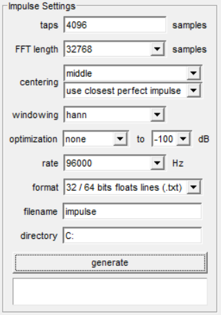
Once you have created your FIR filter in rePhase you will need to specify the settings before exporting it for DSPconfig to convolve. An example of the settings for an output channel is shown below. The tap count and the rate in it are that example's, not ceilings; the ceilings are in the reference's Capacities table.
The number of taps is the setting to think about, because taps are the resource a FIR filter spends and the pools they come from are shared between channels. You do not have to work the budget out in advance: DSPconfig tracks what you have spent, shows it against what is available as you import, and will tell you if a filter does not fit in what is left. The pools themselves are in the reference's Capacities table, and they depend on the sampling rate the profile is running at.
The rate should be set to the processing rate used on your profile.
The format should be 32 / 64 bits floats lines (.txt).
Keeping DSPconfig and Your Firmware Current
DSPconfig and the firmware on your DSP are updated separately, and both are worth keeping current.
DSPconfig is updated regularly with improvements and enhancements. It checks for a newer version each time it starts, and you can check at any time from Help → Check for Updates. Either way it opens a window reporting the version you are running against the latest published one, with a link to the download when there is a newer one. DSPconfig does not update itself: the link goes to the same downloads page you installed from. Both the startup check and the Caution notice can be turned off under File → Preferences.
Your DSP's firmware is upgraded through 'Device → Firmware…', which reports the version the device is running and offers an upgrade when DSPconfig carries a newer one. It is also offered to you: a device that connects with an upgrade waiting gets a notification naming that same menu path.
The upgrade itself takes a few seconds. Save any profile you are working on first, because unsaved editor changes are lost, and do not unplug the device or quit DSPconfig while it runs. A device on firmware 1.5 or earlier does not restart itself afterwards; DSPconfig says so, and the device has to be turned off and on again with the switch on the back before you can carry on. Firmware 1.6 and later restart themselves.
It is worth doing rather than deferring. Firmware 1.6 is what adds 'Device → Settings' with the display and output settings in it, and the firmware a device runs decides one of the capacity figures in the reference, so an upgrade can be the difference between a filter that fits and one DSPconfig refuses.
Further reading
- DSPconfig Reference - every window and every control in turn, and the capacity figures for both models.
- FIR vs IIR Crossovers in Active Loudspeaker Design - when to reach for each filter type in crossover and correction work.
- How does the DSP-8C compare to the miniDSP Flex Eight?
If you have any issues, please contact us at [email protected].